(b) segment pins have a constant-current control. This means that the segment pins are likely to be overloaded if one does not pay attention (a) digit pins are rated for the whole 8-segment current (at full-load, a digit pin carries current 8*Iseg for 1/8 of the time, while a segment pin carries Iseg for the whole time). The digit (common cathode) pins and the segment pins on the MAX have two important differences: Your solution is a clever trick software-wise, however I feel the need to draw attention to a pair of points that should not be overlooked. This entry was tagged 7 segment, 840 segment display, Arduino, LED, max7219. Here's my final setup controlling 8 common anode digits : It's possible to address up to 8 digits with one max7219. for out chosen number to display get it's segment bit at the position current position of 'each_segment'īool seg= number_seg & (0b00000001 << (each_segment-1) ) PinMode(chip_select,OUTPUT) // chip selectįor (byte each_segment=1 each_segment<=8 each_segment++)įor (byte digits = 0 digits < 4 digits++)īyte number_to_display = display_num Void MAX7219Send(uint8_t address, uint8_t value) Controlling a common anode 4 digit 7seg display with the Max7219īyte chip_select=10 // spi chip select pinīyte display_num // array to hold our 4 digits
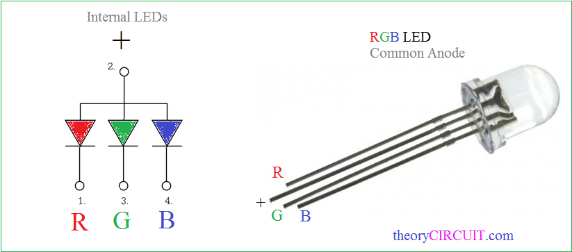
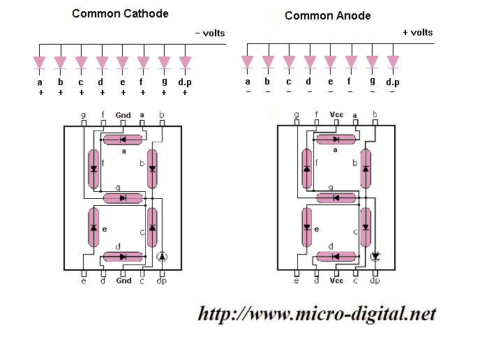
Common anode vs common cathode code#
I've written some basic code for the Arduino (but the same principle will work with the Raspberry Pi) to send numbers to each digit position on my 4 digit module. I need to send the 8 bit segment data across all digit pins, so : As the segments are now connected to the digit pins on the max7219. Or, to digit 2 : MAX7219Send(2,0b00001000) // sends bit 4 / seg D, to digit 2Ĭlearly this isn't going to work with the new wiring. Normally (with bcd mode off) to turn on, say, segment C on digit 1 you would just send 0b00000100 to digit 1.Ī simple spi transfer command might be : MAX7219Send(1,0b00000100) // sends bit 3 / seg C, to digit 1


Set the max7219 decode mode register 0x09 to 0. Goes without saying as each segment will need to be addressed individually. All segment pins on the max7219 now connect to the common anode pins on the display and all digit pins on the max7219 connect to the segment cathode pins on the display. Simple right? Just flip anode and cathode connections on the IC. Or does it? With a little effort and some mind-bending thinking the max7219 can be persuaded to control these common anode displays too. I eventually realised that the max7219 is designed for common cathode displays only, it doesn’t work at all with common anode displays. Hopefully, this has helped you work out what type of display you've got, and now you can get back to business.How to drive common anode displays with the Max7219 and an Arduinoįinding myself with a bunch of common anode 7 segment displays and some left over max7219s, I was soon scratching my head wondering why I couldn’t get anything working.

Below is a graphical diagram that shows the standard letter assigned to each of the segments and a very common wiring arrangement. Pinouts used for most 7segment displaysįor most displays, the wiring will look somewhat like the example. If your display is common ANODE, then you'll have to reverse the logic when you write to it, as a HIGH value will be OFF, and a LOW value will be ON. You can check all segments are working using the same technique, just connect to each of the A-G pins in turn (using the correct polarity of course). If the LED has not lit up in either example then it is potentially broken. So swap the two wires over on the battery or supply, if the LED lights up now it is common CATHODE. If no segment lights up then you need to reverse the wiring. If the LED lights up, it is common ANODE. Next, connect the resistor to the positive terminal (either battery or supply) and then connect any of the A-G segments to 0V or GND. This will avoid potential damage to the LED's in the display. This is easily done with a low voltage supply (9V or less) from a battery, bench PSU or Arduino board.įirstly and before anything else, connect a 1K resistor between the common pin and the battery. If you've got a 7 segment display but are not sure if it is common anode or common cathode, then you need to check the polarity of the display.


 0 kommentar(er)
